

 English
 русский
The evaporator is the core heat-exchange component of any air cooler — it is where refrigerant absorbs heat from the surrounding air, producing the cooling effect. Whether you are selecting an evaporator for a cold storage room, a commercial display case, an industrial process cooler, or a residential air conditioning unit, the evaporator's coil geometry, fin spacing, material construction, and airflow design directly determine how efficiently and reliably the system cools. Choosing the wrong evaporator — undersized, wrong fin pitch for the application temperature, or incompatible with the refrigerant — leads to frost buildup, insufficient cooling capacity, excessive energy consumption, and premature component failure. This article explains how air cooler evaporators work, the main types available, critical specifications, and a practical selection framework.
Content
- 1 How an Air Cooler Evaporator Works
- 2 Main Types of Air Cooler Evaporators
- 3 Critical Specifications for Air Cooler Evaporators
- 4 Fin Pitch Selection by Application Temperature
- 5 Defrost Systems: Types, Energy Impact, and Selection
- 6 Coil Material Options and Corrosion Considerations
- 7 Common Failure Modes and Troubleshooting
- 8 How to Select the Right Air Cooler Evaporator
How an Air Cooler Evaporator Works
An air cooler evaporator operates on the principle of latent heat absorption. Liquid refrigerant enters the evaporator coil at low pressure through an expansion device (thermostatic expansion valve or electronic expansion valve). As the refrigerant flows through the coil, it absorbs heat from the warm air passing over the coil's external surface. This heat absorption causes the refrigerant to evaporate — transitioning from liquid to vapor — while the air leaving the coil is significantly cooler than the air entering it.
The efficiency of this process depends on the temperature difference (ΔT) between the evaporating refrigerant and the incoming air, the surface area available for heat transfer, and the velocity and volume of air moving across the coil. A larger coil surface area allows for a smaller ΔT while still achieving the required cooling capacity — which is thermodynamically more efficient and reduces the compressor's workload.
The Role of Fins and Tubes in Heat Transfer
The evaporator coil consists of refrigerant-carrying tubes — typically copper or aluminum — threaded through a series of closely spaced metal fins, usually aluminum. The fins dramatically increase the effective heat transfer surface area: a typical evaporator with 4 fins per centimeter (approximately 10 FPI — fins per inch) can achieve a surface area 10–20 times greater than bare tubes alone. The fan or blower forces air across this finned surface, maximizing convective heat transfer between the warm air stream and the cold refrigerant inside the tubes.
Tube diameter, tube spacing (pitch), number of refrigerant circuit passes, and fin geometry (flat, wavy, louvered, or lanced) are all engineered variables that manufacturers optimize for specific application temperature ranges and airflow conditions.
Main Types of Air Cooler Evaporators
Air cooler evaporators are categorized by their construction, airflow direction, and intended application temperature range. Selecting the correct type is the first and most consequential specification decision.
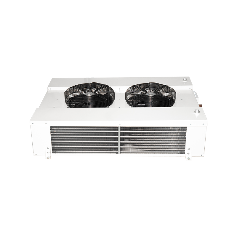
Unit Coolers (Forced-Air Evaporators)
Unit coolers are self-contained evaporator assemblies comprising the coil, one or more fans, a drain pan, and a housing. They are the standard solution for cold storage rooms, refrigerated warehouses, walk-in coolers, and blast freezers. Air is drawn or blown across the coil by integral fans, and the cooled air is distributed into the refrigerated space. Unit coolers are available in top-discharge, bottom-discharge, and horizontal-discharge configurations to suit different room geometries and air distribution requirements.
Bare-Tube Evaporators
Bare-tube evaporators use refrigerant pipes without fins. They are used in applications where frost or ice accumulation would rapidly block finned surfaces — such as open freezer display cases or ice-making equipment — or where the cooled medium is a liquid rather than air. Their heat transfer efficiency per unit volume is lower than finned coils, but they are self-defrosting in many configurations and require minimal maintenance.
Plate Evaporators
Plate evaporators use flat refrigerant channels between two metal sheets, creating a large flat cooling surface. They are common in household refrigerators, small display merchandisers, and applications requiring a smooth, easy-to-clean surface. Plate evaporators offer compact packaging and are inherently frost-tolerant when used as freezer compartment liners.
Flooded vs. Dry-Expansion Evaporators
In a dry-expansion (DX) evaporator, refrigerant enters as a liquid-vapor mixture and exits as superheated vapor; the expansion valve meters refrigerant to ensure complete evaporation within the coil. This is the most common configuration for air coolers. In a flooded evaporator, the coil is kept full of liquid refrigerant at all times, with vapor rising to a surge drum above; heat transfer efficiency is higher (typically 15–30% better than DX), but the system requires more refrigerant charge and is primarily used in large industrial and ammonia refrigeration systems.
Critical Specifications for Air Cooler Evaporators
Reading an evaporator datasheet accurately requires understanding which parameters actually drive performance for a given application — and which are nominal values that change significantly with operating conditions.
| Specification | Typical Range | Practical Significance |
|---|---|---|
| Cooling Capacity (kW) | 0.5–200+ kW | Must be rated at actual ΔT₁ for your application, not nominal conditions |
| ΔT₁ (Air-to-Refrigerant Temp. Difference) | 4–12 K (medium temp); 6–10 K (low temp) | Lower ΔT₁ = less frost, better humidity retention; higher ΔT₁ = more capacity per coil size |
| Fin Pitch (FPI or mm) | 4–12 FPI | Wider spacing (4–6 FPI) for freezer/frost conditions; closer spacing (8–12 FPI) for medium temp/air conditioning |
| Airflow Rate (m³/h) | 500–50,000+ m³/h | Determines air change rate in refrigerated space; affects humidity distribution and product drying |
| Defrost Method | Electric, hot gas, air defrost | Determines energy use, defrost cycle frequency, and suitability for temperature-sensitive products |
| Coil Material | Copper tube/Al fin; Al tube/Al fin; stainless | Affects corrosion resistance, cost, and compatibility with refrigerant and environment |
| Refrigerant Compatibility | R404A, R134a, R448A, R744 (CO₂), NH₃, etc. | Coil design, tube wall thickness, and materials must match refrigerant operating pressures |
Understanding ΔT₁ and Why It Changes Capacity
Evaporator capacity is not a fixed value — it changes with the temperature difference between the room air and the evaporating refrigerant (ΔT₁). A unit rated at 10 kW at ΔT₁ = 10 K will only deliver approximately 6 kW at ΔT₁ = 6 K. Many manufacturers publish capacity tables at a single nominal ΔT₁ (often 10 K), which can lead to significant undersizing if the designer's target ΔT₁ differs. Always verify capacity at the actual operating ΔT₁ for your application — obtainable from the manufacturer's full selection software or detailed capacity tables.
Fin Pitch Selection by Application Temperature
Fin pitch is one of the most application-critical specifications for an air cooler evaporator. In applications where the evaporator surface temperature drops below the dew point of the surrounding air, moisture from the air freezes onto the fins as frost. If the fin spacing is too narrow, frost rapidly bridges the gaps between fins, blocking airflow and collapsing the coil's heat transfer performance within hours.
| Application | Room Temp. Range | Evaporating Temp. | Recommended Fin Pitch |
|---|---|---|---|
| Air conditioning / comfort cooling | 18–28°C | +2 to +10°C | 8–14 FPI (1.8–3.2 mm) |
| Chilled produce storage (high humidity) | 0 to +8°C | -5 to +2°C | 6–8 FPI (3.2–4.2 mm) |
| Meat/dairy medium-temp storage | 0 to +4°C | -8 to -4°C | 5–7 FPI (3.6–5.0 mm) |
| Frozen food storage | -18 to -22°C | -28 to -35°C | 4–5 FPI (5.0–6.3 mm) |
| Blast freezing | -35 to -45°C | -42 to -52°C | 3–4 FPI (6.3–8.5 mm) |
Defrost Systems: Types, Energy Impact, and Selection
Any evaporator operating below 0°C will accumulate frost on its fin surface over time. The defrost system melts this frost and drains the water, restoring full airflow and heat transfer capability. Defrost method selection has a major impact on system energy consumption, product temperature stability, and maintenance requirements.
Electric Defrost
Electric resistance heaters are embedded in or around the coil and drain pan. Simple, reliable, and low-cost to install, electric defrost is the most common method for small and medium commercial unit coolers. The main disadvantage is energy consumption: electric defrost converts electrical energy directly to heat, which the refrigeration system must then re-remove. In a heavily frosting application requiring 4 defrost cycles per day at 30 minutes each, electric defrost heaters can account for 15–25% of total system energy consumption.
Hot Gas Defrost
Hot gas defrost diverts hot high-pressure refrigerant vapor from the compressor discharge directly through the evaporator coil, melting frost from the inside out. It is significantly faster than electric defrost (typically 10–15 minutes vs. 20–45 minutes for electric) and uses heat that the compressor is generating anyway rather than consuming additional electrical energy. Hot gas defrost is the preferred method for large industrial cold stores, multi-temperature distribution centers, and ammonia systems where energy efficiency and minimal temperature pull-up are priorities.
Air Defrost (Off-Cycle Defrost)
In medium-temperature applications (above approximately +2°C room temperature), frost accumulation is slow enough that simply switching off the refrigeration and allowing ambient air to flow across the coil is sufficient to melt accumulated frost between compressor cycles. Air defrost requires no additional energy input and eliminates heater maintenance, but it is only practical in medium-temperature applications where the room air is warm enough to melt frost effectively without excessive temperature rise in the refrigerated space.
Coil Material Options and Corrosion Considerations
The combination of tube and fin materials determines the evaporator's corrosion resistance, heat transfer performance, weight, and cost. The choice matters most in aggressive environments such as food processing facilities, marine applications, ammonia systems, and coastal installations.
- Copper tube / aluminum fin (Cu-Al): The traditional standard for commercial refrigeration; copper offers excellent thermal conductivity and ease of brazing, while aluminum fins provide a cost-effective heat transfer surface. Galvanic corrosion at the Cu-Al interface can occur in high-humidity or acidic environments; epoxy coating of the fin pack mitigates this.
- All-aluminum (Al tube / Al fin): Increasingly common in newer systems; eliminates galvanic corrosion, reduces weight by approximately 30–40% vs. Cu-Al, and is compatible with modern HFC and HFO refrigerants. Requires careful pH control of defrost water as aluminum is sensitive to both acidic and alkaline conditions.
- Stainless steel tube / aluminum fin: Used in food processing environments where cleaning chemicals, brine, or CO₂ (which forms carbonic acid) create aggressive corrosion conditions for standard materials. Higher cost but significantly extended service life in harsh environments.
- Epoxy or Blygold-coated fin packs: A cost-effective corrosion protection option for Cu-Al or Al-Al coils in coastal, marine, or chemically aggressive environments; adds 3–8 years to typical fin pack service life in moderate corrosion conditions.
- Stainless steel full construction: Required for ammonia (NH₃) systems, as ammonia attacks copper rapidly; stainless or carbon steel tubes with stainless fins are the standard for industrial ammonia evaporators.
Common Failure Modes and Troubleshooting
Understanding the typical failure modes of air cooler evaporators allows maintenance teams to diagnose problems faster and implement preventive measures that extend equipment life.
Frost Bridging and Airflow Blockage
Frost bridging — where ice completely blocks the gaps between fins — is the most common operational issue in low-temperature evaporators. It manifests as reduced airflow, rising room temperature despite the compressor running, and a visible ice block on the coil face. Root causes include defrost cycle failure (faulty heater, timer, or termination thermostat), excessive door opening frequency admitting humid air, or an undersized defrost system relative to the actual frost load. Corrective action requires a full manual defrost, followed by root cause investigation before returning the system to automatic operation.
Fin Corrosion and Coil Leaks
Fin pack corrosion progresses from surface oxidation to pin-hole leaks in the refrigerant tubes over time, particularly in coastal or chemically aggressive environments. Early signs include white or grey powdery deposits on aluminum fins and a gradual decline in cooling capacity as the effective heat transfer area diminishes. Refrigerant leaks from corroded tube walls result in loss of system charge, reduced capacity, and potential environmental release of refrigerant. Annual visual inspection of the fin pack and quarterly leak detection checks with an electronic refrigerant detector are best practice for evaporators in corrosive environments.
Drain Pan Blockage
Defrost water must drain freely from the evaporator drain pan through the drain line to avoid re-freezing in the pan, which can damage the pan itself or cause water to overflow onto the floor or product. Drain pan blockages are caused by algae growth, food debris, or ice formation in the drain line. Drain line heaters (electric trace or hot gas) prevent freezing in below-0°C applications. Quarterly drain pan cleaning and monthly verification of drain flow are recommended maintenance intervals for commercial cold store evaporators.
How to Select the Right Air Cooler Evaporator
A structured selection process prevents the most common specification errors — oversizing (which causes excessive frost and humidity loss), undersizing (which leads to inability to maintain set temperature under peak load), and wrong fin pitch for the application temperature.
- Calculate the total heat load: Sum all heat sources entering the refrigerated space — transmission through walls and roof, product load, infiltration from door openings, internal equipment (lights, fans, motors), and people if present. This is the cooling capacity the evaporator must match or exceed.
- Define the operating ΔT₁: Determine the target room temperature and the acceptable evaporating temperature (which sets ΔT₁). Lower ΔT₁ (5–7 K) preserves product humidity better; higher ΔT₁ (10–12 K) allows smaller coil selection but dries products faster and requires a colder evaporating temperature, increasing compressor energy consumption.
- Select fin pitch based on application temperature: Use the fin pitch guidance table above; err toward wider fin spacing if in doubt, as a coil with wider fins that defrosts less frequently will outperform a coil with narrow fins that blocks rapidly.
- Choose defrost method: Electric defrost for small and medium commercial applications; hot gas defrost for large industrial systems or where energy efficiency is critical; air defrost only for medium-temperature rooms above +2°C.
- Specify coil material for the environment: Standard Cu-Al for general commercial use; consider coated or all-aluminum for humid or mildly corrosive environments; stainless for food processing, brine, or ammonia systems.
- Verify capacity at actual operating conditions: Confirm the selected unit's capacity from the manufacturer's full rating tables at your specific ΔT₁, room temperature, and refrigerant — not just the headline nominal capacity figure on the product page.

