

 English
 русский
A refrigeration air cooled unit is the most practical and widely deployed cooling system for commercial and industrial applications where water supply is limited or where simplified maintenance is a priority. The system works by rejecting heat from the refrigerant directly into the ambient air, eliminating the need for a cooling tower or condenser water loop. The three core components that define the system are the air cooled condenser, the air cooler evaporator, and the compressor assembly packaged together in air cooled condensing units. Understanding how each component functions, how they interact, and how to select the right configuration will directly determine energy efficiency, operating cost, and system lifespan.
Content
- 1 How a Refrigeration Air Cooled Unit Works
- 2 Refrigeration Air Cooled Condenser: Design and Function
- 3 Air Cooler Evaporator: Performance Inside the Refrigerated Space
- 4 Air Cooled Condensing Units: Packaged System Advantages
- 5 Key Performance Metrics and How to Evaluate Them
- 6 Installation Best Practices for Air Cooled Systems
- 7 Maintenance Schedules That Protect System Performance
- 8 Selecting the Right System: A Decision Framework
How a Refrigeration Air Cooled Unit Works
The refrigeration cycle in an air cooled system follows the same fundamental vapor-compression principle as water-cooled alternatives, but with one critical distinction: ambient air serves as the heat sink instead of water. The refrigerant absorbs heat inside the refrigerated space through the evaporator, travels to the compressor where its pressure and temperature are raised, then releases that heat to outdoor air through the condenser coil before returning to the evaporator to repeat the cycle.
This air-side heat rejection makes the system inherently dependent on ambient temperature. As outdoor temperatures rise, the condensing pressure increases, the compressor works harder, and system efficiency drops. This relationship is quantified by the coefficient of performance (COP), which for a typical air cooled refrigeration unit ranges from 2.0 to 3.5 under standard conditions (outdoor ambient of 35 degrees C, evaporating temperature of minus 10 degrees C), compared to 4.0 to 5.5 for equivalent water-cooled systems. The trade-off is accepted because of lower installation cost, no water treatment requirement, and simpler regulatory compliance.
Refrigeration Air Cooled Condenser: Design and Function
The refrigeration air cooled condenser is the component responsible for transferring heat from the hot refrigerant gas to the surrounding air. It consists of a coil assembly, typically constructed from copper or aluminum tubes with aluminum fins, through which the hot discharge gas from the compressor flows and condenses into a liquid state. One or more axial fans draw or push ambient air across the coil to accelerate this heat transfer process.
Condenser Coil Construction and Materials
Coil geometry has a direct impact on thermal performance. Fin density is measured in fins per inch (FPI), with most commercial refrigeration condensers operating in the range of 8 to 14 FPI. Higher fin density increases surface area and heat transfer capacity but also increases airflow resistance, which can reduce fan efficiency and cause fouling in dusty environments. In coastal or industrial environments with corrosive atmospheres, epoxy-coated or electro-fin treated coils are specified to resist oxidation and extend service life by 3 to 5 years compared to untreated aluminum fin stock.
Fan Configuration: Draw-Through vs. Blow-Through
Condenser fans are arranged in either draw-through or blow-through configurations. In draw-through designs, fans are positioned downstream of the coil and pull air across the heat exchange surface. This is the more common arrangement for refrigeration condensers because the uniform airflow distribution across the coil improves heat transfer efficiency. Blow-through configurations, where fans push air into the coil, are used in space-constrained installations but can create uneven airflow distribution and hot spots on the coil surface. Fan motor efficiency is a significant energy cost factor; modern EC (electronically commutated) fan motors reduce condenser fan energy consumption by 30 to 50% compared to legacy AC shaded-pole motors.
Subcooling and Its Impact on System Efficiency
A well-designed air cooled condenser should provide 5 to 10 degrees C of liquid subcooling at the condenser outlet under design conditions. Subcooling reduces flash gas formation at the expansion device, increasing refrigeration effect per unit of refrigerant mass flow. Each additional degree of subcooling improves system capacity by approximately 0.5%, a measurable benefit over a full operating season.
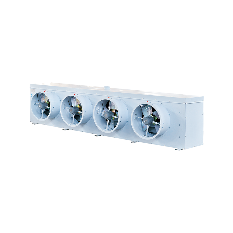
Air Cooler Evaporator: Performance Inside the Refrigerated Space
The air cooler evaporator is the heat exchanger installed inside the refrigerated space, where it absorbs heat from the stored product and the room air to evaporate the refrigerant. Unlike condensers, which primarily handle sensible heat rejection to outdoor air, evaporators in refrigeration systems must manage both sensible cooling and latent heat (moisture removal), making their selection more application-specific.
Evaporator Types by Application
Air cooler evaporators are broadly categorized by their target temperature range and defrost requirements:
- Medium-temperature evaporators (0 to 10 degrees C room temperature): Used in produce coolers, dairy rooms, and walk-in refrigerators. Operate with evaporating temperatures between minus 5 and minus 15 degrees C. Typically use electric or hot gas defrost with 2 to 4 defrost cycles per day.
- Low-temperature evaporators (minus 18 to minus 25 degrees C room temperature): Used in blast freezers, frozen food storage, and ice cream storage. Evaporating temperatures of minus 30 to minus 40 degrees C. Heavy frost accumulation requires more aggressive defrost strategies including hot gas or electric defrost with 3 to 6 cycles daily.
- Process cooling evaporators: Designed for industrial applications requiring precise temperature control, often with stainless steel construction for food-grade or pharmaceutical compliance.
Temperature Difference and Coil Surface Area
The temperature difference (TD) between the air entering the evaporator and the refrigerant evaporating temperature is a key design parameter. A large TD (10 to 15 degrees C) results in a smaller, less expensive coil but causes significant dehumidification, which is detrimental to fresh produce storage. A small TD (3 to 6 degrees C) requires a larger coil surface area and higher refrigerant flow but preserves product moisture. For fresh meat and produce cold rooms, specifying a TD of 4 to 6 degrees C is a widely accepted best practice to minimize weight loss from product dehydration, which can amount to 1 to 3% of product weight per week in poorly designed installations.
Airflow Distribution Inside the Cold Room
An air cooler evaporator must distribute conditioned air uniformly throughout the refrigerated space to prevent warm spots and temperature stratification. Ceiling-mounted unit coolers with forward-throw fans are the standard configuration for cold rooms up to 500 cubic meters. For larger spaces, multiple evaporator units are arranged to create overlapping airflow patterns, ensuring no dead zones exceed the design temperature by more than plus or minus 1.5 degrees C, which is the tolerance required for most food safety standards including HACCP compliance.
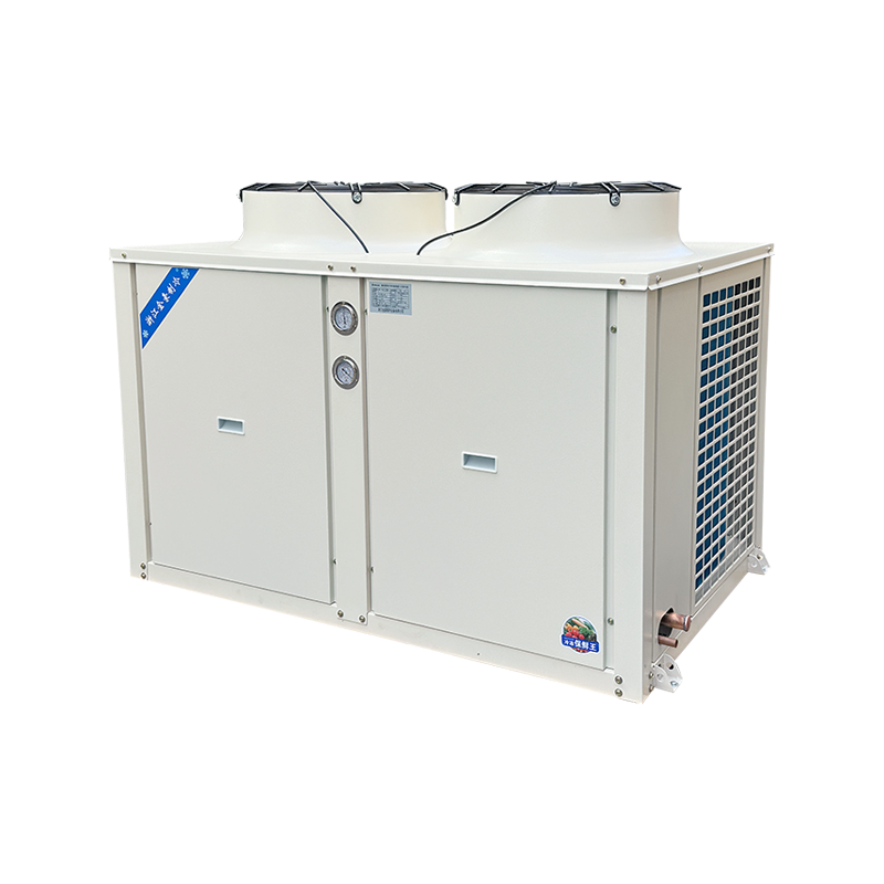
Air Cooled Condensing Units: Packaged System Advantages
Air cooled condensing units combine the compressor, air cooled condenser, receiver, and associated controls into a single factory-assembled package. This integration reduces field installation time, simplifies commissioning, and ensures that the compressor and condenser are correctly matched for the refrigerant and application before leaving the factory.
Single-Compressor vs. Multi-Compressor Units
Condensing units are available with a single compressor or with multiple compressors in parallel (also called rack or multi-circuit units). The choice has significant implications for redundancy and part-load efficiency:
| Feature | Single-Compressor Unit | Multi-Compressor Unit |
|---|---|---|
| Capacity Range | 0.5 to 50 kW | 20 to 200+ kW |
| Part-Load Efficiency | Lower (on/off cycling) | High (staging compressors) |
| Redundancy | None without standby | Built-in (N-1 operation) |
| Installation Cost | Lower | Higher |
| Best Application | Small cold rooms, convenience retail | Supermarkets, distribution centers |
Refrigerant Selection for Modern Condensing Units
The refrigerant used in air cooled condensing units affects both system efficiency and regulatory compliance. The global phase-down of high-GWP HFCs under the Kigali Amendment to the Montreal Protocol is accelerating the transition to lower-GWP alternatives. Current market trends for commercial refrigeration units show:
- R-404A (GWP 3922): Still in service in many legacy systems but being phased out in Europe under F-Gas regulations. Replacement retrofits to R-448A or R-449A are common.
- R-448A / R-449A (GWP approx. 1273 and 1282): Drop-in replacements for R-404A in medium and low-temperature condensing units, offering 5 to 12% higher energy efficiency in most applications.
- R-744 (CO2, GWP 1): Increasingly used in transcritical configurations for supermarket rack systems in climates below 30 degrees C ambient. Requires specialized high-pressure components but offers the lowest environmental impact.
- R-290 (Propane, GWP 3): Gaining adoption in small hermetic condensing units (below 5 kW) due to excellent thermodynamic properties and near-zero climate impact, subject to charge size limits of 150 grams per circuit.
Key Performance Metrics and How to Evaluate Them
When specifying or comparing air cooled refrigeration systems, five metrics are most critical for making an informed decision.
| Metric | Definition | Typical Value (Air Cooled) | Significance |
|---|---|---|---|
| COP | Cooling output divided by power input | 2.0 to 3.5 | Primary energy efficiency indicator |
| Condensing Temperature | Refrigerant temperature at condenser | 40 to 55 degrees C | Higher = lower COP and higher compressor load |
| Evaporating Temperature | Refrigerant temperature at evaporator | Minus 40 to 0 degrees C | Lower = more compressor work required |
| ESEER / SEPR | Seasonal efficiency rating | Varies by application | Better reflects real-world annual energy use |
| Sound Power Level | Noise output of the condensing unit | 60 to 75 dB(A) at 10 m | Critical for urban or residential-adjacent sites |
A practical rule of thumb often cited by refrigeration engineers: every 1 degree C reduction in condensing temperature improves system COP by approximately 2 to 3%. This makes condenser sizing and positioning one of the highest-return design decisions in an air cooled refrigeration project.
Installation Best Practices for Air Cooled Systems
Poor installation is one of the leading causes of underperformance in refrigeration air cooled units. The following practices are critical to achieving rated system performance:
Condenser Unit Placement and Airflow Clearance
Air cooled condensers must be positioned to allow unrestricted airflow to the inlet and free discharge of hot exhaust air away from the unit. Recirculation of hot discharge air back to the condenser inlet is one of the most common and damaging installation errors. It can raise the effective ambient temperature at the condenser by 5 to 15 degrees C, causing a corresponding increase in condensing pressure and compressor power consumption of up to 25%.
- Maintain a minimum clearance of 1.0 meter on all air inlet sides of the condensing unit.
- Discharge air must not be directed toward walls, fences, or other obstructions within 2.0 meters of the fan outlet.
- When multiple condensing units are installed in rows, use manufacturer-specified spacing to prevent cross-recirculation between adjacent units.
- In rooftop installations, prevailing wind direction should be factored into unit orientation to avoid wind-induced recirculation.
Refrigerant Pipework Sizing and Insulation
Suction line sizing between the evaporator and condensing unit directly affects system performance. Undersized suction lines create excessive pressure drop, effectively lowering the suction pressure at the compressor and reducing evaporating temperature. A pressure drop equivalent to 1 degree C in saturation temperature on the suction line is the maximum typically permitted by system designers. All suction lines must be insulated with closed-cell foam insulation of at least 19 mm wall thickness to prevent heat gain and condensation.
Electrical Supply and Voltage Tolerance
Air cooled condensing units are sensitive to voltage fluctuations, particularly during compressor start-up. Most manufacturers specify a voltage tolerance of plus or minus 10% of nominal supply voltage. Voltage imbalance between phases in three-phase units should not exceed 2%, as higher imbalance causes disproportionate heating in compressor windings and significantly reduces motor life. A dedicated circuit with appropriate fusing and disconnection, sized at 125% of full-load current, is the standard requirement for condensing unit power supply.
Maintenance Schedules That Protect System Performance
Consistent preventive maintenance is the single most cost-effective action for preserving the performance and extending the service life of an air cooled refrigeration system. Studies of commercial refrigeration installations show that neglected condenser coils alone can reduce system efficiency by 15 to 30% within 12 to 24 months of installation in urban or industrial environments.
A recommended maintenance schedule for air cooled condensing units and their associated evaporators is as follows:
- Monthly: Inspect and clean condenser coil face for debris, dust, and cottonwood. Check fan blade condition and tighten fasteners. Verify evaporator defrost completion and drain pan drainage.
- Quarterly: Measure and record suction and discharge pressures, superheat, and subcooling. Compare against design values to detect refrigerant charge loss or fouled heat exchangers. Check electrical connections for corrosion and tightness.
- Annually: Deep-clean condenser coil with coil cleaner and low-pressure water rinse. Inspect compressor oil level and quality. Test all safety controls including high-pressure cutout, low-pressure cutout, and motor overloads. Verify refrigerant charge by weight or subcooling measurement.
Leak testing is particularly important given tightening F-Gas regulations in the EU and equivalent regulations in other jurisdictions. Systems with a refrigerant charge above 5 metric tons CO2 equivalent are required to undergo leak checks at least once every 12 months, and systems above 50 metric tons CO2 equivalent every 6 months.
Selecting the Right System: A Decision Framework
Choosing the correct configuration of air cooled condensing unit and evaporator for a specific application requires evaluating six interconnected variables. Working through them in order reduces the risk of undersizing or oversizing the system.
- Define the required room temperature and product load. Establish whether the application is medium-temperature (0 to 10 degrees C) or low-temperature (minus 18 to minus 25 degrees C), and calculate the total heat load including product pull-down, transmission gains, infiltration, and internal heat sources.
- Establish the design ambient temperature. Use the 99th percentile summer design dry-bulb temperature for the installation location, not the average. In many parts of the Middle East, for example, design ambient temperatures of 45 to 50 degrees C must be used, requiring oversized condensers and high-ambient-rated compressors.
- Select the refrigerant. Consider regulatory trajectory, required evaporating temperature, system scale, and available service infrastructure before committing to a refrigerant. Future-proof selections favor low-GWP options where technically and commercially viable.
- Size the evaporator for the required TD and airflow. Match coil surface area to the load while controlling TD to protect product quality. Specify defrost type, frequency, and duration based on room humidity and operating temperature.
- Select and position the condensing unit. Use manufacturer selection software to choose a unit whose rated capacity at the design condensing and evaporating temperatures meets or slightly exceeds the calculated load. Verify sound power levels against site constraints.
- Verify pipe sizing and system controls. Confirm that suction, discharge, and liquid line sizes are within allowable pressure drop limits. Specify electronic expansion valves and a digital controller for systems requiring tight temperature control or remote monitoring capability.

